Latest News
The latest and greatest project news
How to Design Hydraulic Power Pack?

How does one design a hydraulic power pack that not only meets but exceeds industry standards? Understanding the core principles of hydraulic power pack design is crucial. It involves considering factors like performance, efficiency, and customization.
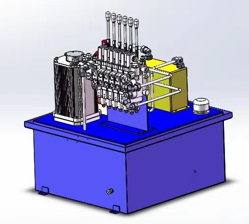
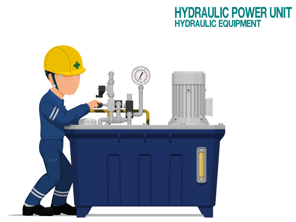
Designing a hydraulic power pack requires a deep understanding of its components, their functions and system requirements. The main components include a reservoir, a pump, a motor, and various control valves. Each part plays a critical role in the overall efficiency and performance of the power pack.
Table of Contents
Hydraulic Circuit Design
2. Select the Right Components: The core components of a hydraulic circuit include a pump, valves (control, pressure relief, check, directional), actuators (cylinders, hydraulic motors), a reservoir, and various connectors and hoses. Choose these components based on the system’s requirements, ensuring they are compatible and meet the needed specifications.


What Are the Key Considerations in Hydraulic Power Pack Design?
1. System Requirements: Understanding the specific needs of the application is essential. This includes the required pressure, flow rate, and power. The design should be tailored to meet these operational requirements efficiently.
2. Component Selection: The choice of components like pumps, motors, valves, and reservoirs is critical. Each component must be compatible with the others and suited to the overall system’s requirements. The durability and quality of these components directly impact the power pack’s performance and longevity.
3. Materials and Construction: The materials used in the power pack should be chosen based on the working environment and the type of fluid used. Durability, corrosion resistance, and strength are important factors. The construction should also facilitate easy maintenance and repair.
4. Reservoir Design: The size and design of the reservoir are important. It should be large enough to allow for proper heat dissipation and settling of contaminants, but also compact enough for the intended application. The design should also consider aspects like fluid dynamics and ease of cleaning.
5. Heat Dissipation: Efficient heat dissipation is essential to maintain the hydraulic fluid’s properties and prevent overheating of the system. This might involve the use of coolers or designing the reservoir and system layout to maximize natural cooling.
6. Energy Efficiency: The power pack should be designed for maximum energy efficiency. This involves selecting the right motor and pump combination, optimizing the system’s hydraulic circuit, and potentially incorporating energy-saving features like variable speed drives.
7. Control and Regulation: The control system must be precise and responsive, including appropriate control valves, pressure regulators, and potentially electronic control systems for complex applications.
8. Safety Features: Incorporate safety features like pressure relief valves, emergency shut-offs, and overload protection to prevent accidents and equipment damage.
9. Noise Reduction: If applicable, implement measures to reduce noise, such as using silencers, special mounts, and design techniques to minimize vibration and noise.
10. Customization and Scalability: The design should allow for customization and scalability to adapt to different applications or changing requirements.
11. Compliance with Standards and Regulations: Ensure the design complies with relevant industry standards and regulations for safety, quality, and ease of approval for various applications.
12. Cost-effectiveness: While maintaining quality and performance, the design should also be cost-effective, offering competitive pricing without compromising functionality and durability.
Hydraulic Power Pack Design Components and Calculations
Key Components of Hydraulic Power Pack
Hydraulic Pump: The pump converts mechanical energy into hydraulic energy. It determines the flow rate and pressure in the system. Common types include gear, vane, and piston pumps.
Motor: Powers the hydraulic pump. The motor’s power rating should match the pump’s requirements. Electric and internal combustion engines are typical choices.
Reservoir: Stores the hydraulic fluid. Its size should accommodate the total system fluid volume, allowing for thermal expansion and fluid contamination settling.
Valves: Control the flow and direction of the hydraulic fluid. Types include directional control valves, pressure relief valves, check valves, and flow control valves.
Actuators: Convert hydraulic energy into mechanical energy. Hydraulic cylinders and motors are common actuators.
Filters: Remove contaminants from the hydraulic fluid to protect the system components and maintain fluid cleanliness.
Cooler or Heat Exchanger: Used if the system generates excessive heat, to maintain the hydraulic fluid at an optimal temperature, including water cooler and air cooler.
Pressure Gauges and Sensors: Monitor system pressure and other parameters for safety and efficiency.
Hoses and Connectors: Transport hydraulic fluid between components. They must be rated for the system’s maximum pressure.
Essential Calculations for Hydraulic Power Pack Design
Flow Rate Calculation:

Pump Power Calculation:

Actuator Sizing:

Reservoir Size Calculation:
Typically, the reservoir should hold at least three times the pump’s flow per minute.
Pressure Drop Calculations:
Calculated using Bernoulli’s principle and considering factors like fluid viscosity, pipe length, diameter, and flow rate.
Heat Load Calculation:

Safety Factor Calculation:
Ensuring components like hoses and connectors are rated for pressures well above the maximum system pressure.
Hydraulic Cylinder Calculations
1. Force Output Calculation
The force exerted by a hydraulic cylinder is a function of the pressure in the system and the area of the cylinder’s piston. It can be calculated using the formula:
Force=Pressure×Piston AreaForce=Pressure×Piston Area
Where:
- Force is in newtons (N) or pounds (lb),
- Pressure is in pascals (Pa) or pounds per square inch (psi),
- Piston Area is in square meters (m²) or square inches (in²).
For a circular piston, the area is calculated as:

2. Cylinder Speed Calculation
The speed at which a hydraulic cylinder extends or retracts depends on the flow rate of the hydraulic fluid and the area of the piston. The formula is:

Where:
- Speed is in meters per second (m/s) or inches per second (in/s),
- Flow Rate is in cubic meters per second (m³/s) or gallons per minute (GPM).
3. Cylinder Extension/Retraction Time Calculation
The time taken for a cylinder to fully extend or retract can be calculated by:

Where:
- Time is in seconds (s),
- Stroke Length is the distance the piston travels, in meters (m) or inches (in).
4. Buckling Load Calculation (for long cylinders)
This calculation is important for ensuring the cylinder can withstand the load without buckling, especially for long strokes or when the cylinder is acting in compression. It’s a more complex calculation involving factors like the cylinder’s length, diameter, and material properties.
5. Hydraulic Power Calculation
The power required for a hydraulic cylinder can be calculated as:

Where:
- Power is in watts (W) or horsepower (HP),
- Efficiency is the overall efficiency of the hydraulic system.
6. Hydraulic Pressure Calculation
If the force output and piston area are known, the required hydraulic pressure can be calculated as:

7. Pump Size Calculation
To determine the appropriate pump size for a hydraulic system with a given cylinder, consider both the flow rate needed to achieve the desired cylinder speed and the pressure required to achieve the necessary force.
Hydraulic Motor Calculations
1. Torque Calculation
The torque output of a hydraulic motor is determined by the pressure of the hydraulic fluid and the motor’s displacement. The formula is:

Where:
- Torque is in newton-meters (Nm) or foot-pounds (ft-lb),
- Displacement is in cubic meters per revolution (m³/rev) or cubic inches per revolution (in³/rev),
- Pressure is in pascals (Pa) or pounds per square inch (psi).
2. Speed Calculation
The speed of a hydraulic motor is determined by the flow rate of the hydraulic fluid and the motor’s displacement:

Where:
- Speed is in revolutions per minute (RPM),
- Flow Rate is in cubic meters per second (m³/s) or gallons per minute (GPM).
3. Power Calculation
The power output of a hydraulic motor can be calculated as:
![]()
Where:
- Power is in watts (W) or horsepower (HP),
- Angular Velocity is in radians per second (rad/s).
To convert RPM to rad/s, use the conversion:

4. Hydraulic Flow Calculation
If the motor’s speed and displacement are known, the required flow rate can be calculated as:
Flow Rate=Speed×DisplacementFlow Rate=Speed×Displacement
5. System Pressure Calculation
If the required torque and motor displacement are known, the system pressure can be calculated as:

Conclusion
Designing a hydraulic power pack is a comprehensive process that requires careful consideration of various technical and practical aspects. The goal is to create a system that is efficient, reliable, and tailored to the specific needs of its intended application.
In essence, a well-designed hydraulic power pack not only meets the specific requirements of its application but also stands the test of time in terms of durability and reliability.
Recent Posts
Share This Story, Choose Your Platform.
Leave A Comment
Your email address will not be published. Required fields are marked *
